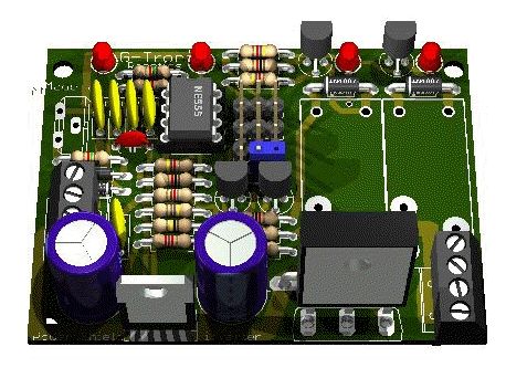
PWM power inverter printed circuit board for controlling the direction of travel and speed of a large DC motor up to 20A (depends on the relays which mount). The recirculation diode is onboard.
Two LEDs indicate the direction of rotation and a third LED illuminates the control.
The circuit can operate autonomously, adding the potentiometer for speed control and buttons / switches for the direction of travel, or it can be connected to an embedded Micro-GT or Arduino system or even to a common PLC.
The first mini shield which, although specific controller for the Micro-GT mini, can actually be interfaced with any microcontroller/microprocessor. Excellent for fairly powerful robotic applications. It also works autonomously, i.e. without the need for a microprocessor control circuit.
The description of the pwm controller is based on the PWM control section presented in a previous chapter of “Let’s GO PIC!!!” given that the circuit is optimal. The implementation is developed based on the NE555 timer. For the motors I normally use (24V DC or 36VDC gearmotors), the optimal operating frequency is 22Khz. For further information on the operation of the NE555 Timer used as a PWM generator, please refer to the eighth chapter of the tutorial.
The electronic board has a switching power control section, useful for controlling the moving parts of small self-propelled robots.
related topics: command and control circuits, controller, DC motors, drive, PCB Design Software eagle, g-tronic, hardware, inverter, micro gt, PCB, PIC, piloting, power, pwm, robot, Switching, system